Here we're starting the build log for the Bench top mill. A quick recap on the spec and goal:
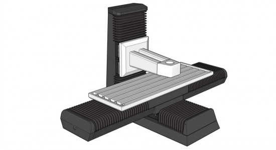
Travels will be roughly 750 x 400 x 400 mm (30 x 16 x 16"). Ball screws are C5 grade ground NSK items, 25 mm dia. and 8 mm pitch. Axis drive motors will be 300 watt brushless servos, driven by Granite Devices VSD-E drives. Feed speeds ~ 500 ipm, resolution .002 mm (0.00008"), Spindle to be confirmed. Frame will be constructed from square section steel bar.
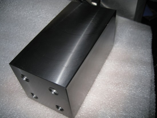
The first part - front cross member and Y axis ball screw floating end bearing support. Milled from 3" square bar stock, the important thing with this part is to ensure the ends are parallel, since the side rails mate with the ends of this part.
A 3.15" 45â° insert face mill does a nice job of chamfering the corners as well as facing the sides and ends, and leaves a nice surface finish for this part.
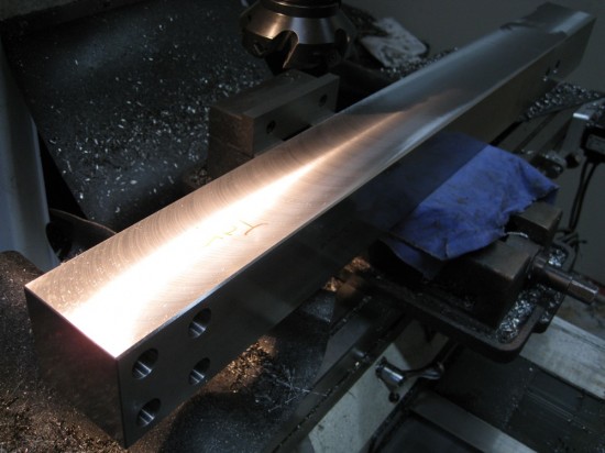
Next: The side bars that will carry the Y axis linear bearing rails.
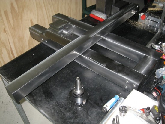
One side done. You'll notice there's no milled rebate for the linear rails yet. That will be cut later, the base will be assembled and machined as a single unit to ensure all critical surfaces are parallel and co-planar.
As this part was longer than the travel of the mill, it had to be machined in two steps. Much care was taken to ensure all surfaces are square and parallel - more work for the 3" face mill. The steel stock is behaving very nicely, with no evidence of any bow or twist so far, and it machines particularly well.
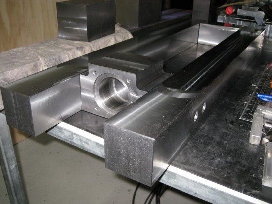
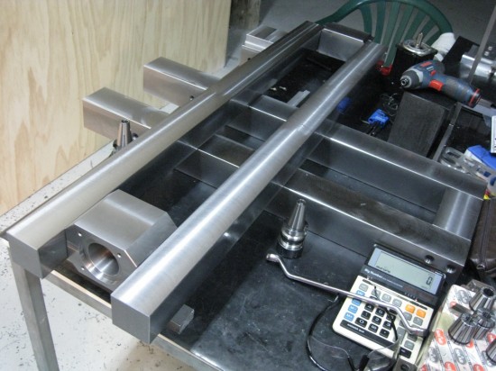
The Servo/Ball screw mounting block is done, and that completes the basic parts for the machine base.
Next job for the base will be to fix them all together and cut the slots for the linear bearing rails, drill the column mounting holes, and drill and tap for the bolts that will fix the linear rails in place. There will also be some tapped holes in the bottom of the base to allow for fixing to the stand, and fixing points for the limit switches and way covers...
First though, a start on the saddle assembly. The new part is one of the two longest jobs for this build, and I wanted to get it underway in case I was unable to get it acceptably accurate over the full length - in which case it would have had to go to an engineering shop with a bigger machine. Fortunately it went well. I used a dial indicator, and with the turret on the big mill rotated 30º I tested the movement of the table as it traversed with the stock mounted. After firmly locking the Z and Y axis, I was able to confirm the X axis was staying very close to level through the full travel, so I went ahead and faced the sides, chamfered the corners and trimmed the ends.
The 2.5" square (63.5 mm) stock has a finished size of 62.5 mm square, so there wasn't much to come off this time. I drilled and counterbored the holes for the cross member (far end in photo, will also house the ball screw's floating end bearing), but left the holes for the servo/fixed bearing mount for now as I need to assemble the mount onto the screw and measure the exact length of the assembly first.
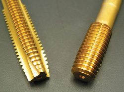
I've now tapped all the threaded holes in the parts so far: after some hesitation I used my thread forming taps. If you're not familiar with these, then you owe it to yourself to check them out. Looking like a normal tap but without the flutes, the thread is formed through metal displacement, essentially a forging process. This has a number of significant advantages: no chips collecting at the bottom of blind holes, no need to back the tap up to break off the chips, and the thread formed is apparently significantly stronger. They are also self-centering to a certain extent. The caveats include needing a precise hole - the diameter must be just right, too small and the tap will bind and break, too big and the thread formed will be too shallow. A good tapping compound is absolutely essential. For the smaller taps I drive them with a cordless drill - very fast, since there's no need to back it out to clear the hole. For the larger threads I use a normal tap handle, but it's still much quicker than conventional taps. My initial hesitation was due to having broken one recently in cast iron - all my other work with them has been in aluminium and I wasn't sure how well they would work in this grade of steel. As it turned out, I needn't have worried - they worked beautifully, and left a very nice result.
Here's a picture of the difference between standard and forming taps - standard on the left, forming on the right. You'll notice some fine grooves running the length of the flutes on the forming tap: these let the tapping fluid escape when tapping a blind hole. There's more reading Here.
Today I chose to make a smaller part after all the heavy lifting of the last few days! This is the end bearing support for the X axis ball screw, which also serves to stabilize the end of the bars that will support the X axis linear rails.
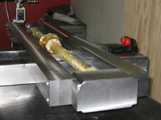
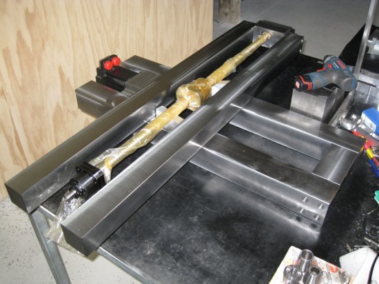
I fitted a Nema34 servo to the Y axis motor mount, and dropped the X ball screw roughly into place, just to confirm things were fitting as they should.
Next up, the X axis servo/ball screw fixed end mounting block, followed by the column. I'm looking forward to having the column done - it'll start to look more interesting then, I think!
Here's that ball screw mounting block - it still needs the other side bored out for the ball screw fixed end support, which houses the dual angular contact bearings that fix the screw in place axially.
Lots of hot chips today!
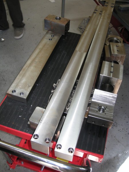
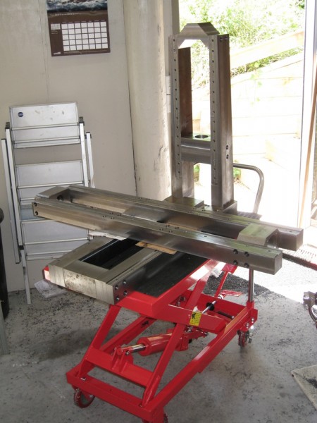
After something of a hiatus, at last there is some progress to report! I need this machine to make some stuff now, so it's underway again. Some parts went a bit rusty, and we have a couple more parts done:
My brother has kindly stepped in to help. The two chunky parts with no rust on the lower right are his first ever machined parts - pretty good, I say!
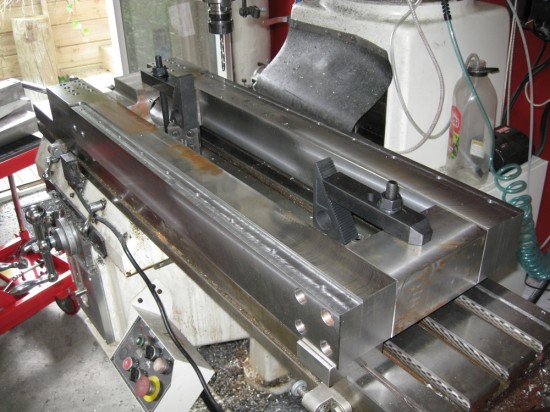
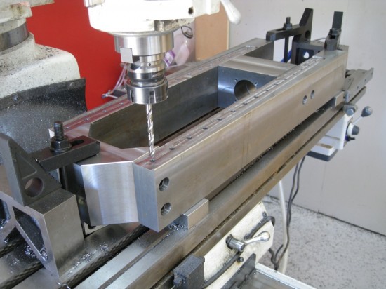
The base assembled on the mill, rebating and drilling for the linear bearing rails.
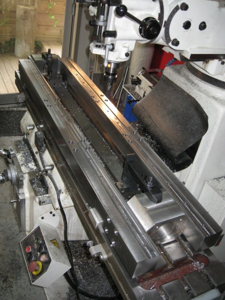
...and same for the X axis.
... and the Z axis. For each of those, we dialled in one long side on the mill table, then clamped it down and bolted the rest of the parts to it, with 123 blocks under each component to accurately locate all parts co-planar.
With the bolts in the assembly just snug, we clamped the rest of the parts down and tightened the bolts up before milling the rebated pads where the linear bearings seat. Each pair of bearings will have one rail clamped against a reference edge, then the other rail will be aligned to that one with a dial gauge.
Let's call that the end of part one. Still to come - Assembly, Stand and enclosure and Electronics!
One more pic.


Comments
Regards,
Jason
Regards,
Jason
Do you plan your lathe built with bigger size such as 14" X 40" with 2" spindle bore? None big lathe has been done in cnc zone, that will be very good built. I keep on watching your built, your micro lathe was very good built.
The next machine will be a lathe, but not quite that big, probably about 10" x 24", with a 40 mm bore.
Best regards,
Jason
Very neat build.
Are you on cnc zone?
You should post pics there, its a heavily biased towards Geckodrive website though.
Hobbycnc from hungary is a top site, darn good machine builders in eastern europe.
I am a member at CNCZone, yes. I hadn't decided whether to post this machine there yet, I may do once it's a little further along.
I hadn't seen the Hobbycnc site, I'll check it out - thanks.
Regards, Jason
I must say your work looks fantastic!!
I am trying to decide what to do
with my Mini cnc (24x24)Router after seeing
your mill at work it looks like the perfect
machine for my 2d projects.
Keep up the great work!!
Regards,
Jason
Regards,
Sven
I do, actually! Well, a couple of them at least :) My user name there is Jason3, and this machine is in the vertical mill/lathe project log section. The micro lathe is there too.
Best regards,
Jason
Any progress on this machine yet? Have you try new GD VSD-E 160? Thanks.
Sorry, regrettably no progress. We had a death in the family, and with the events leading up to and following, not much has happened at all.
We have stock of the new VSD-E 160 on the way, so should get to try it soon.
Best regards,
Jason
Are plans available for this project or just the smaller mill?
Todd
I'm sorry, we haven't drawn up step by step or individual component plans for this machine - I have been working from the 3D model that the first picture in this post was taken from.
Best regards,
Jason
Are the plans for the other mill on hold as well?
Todd
Best regards,
Randy
Randy - thank you very much.
Best regards,
Jason
Ferry - thank you for your complement! You're welcome to copy it, and please do head over to www.zealcnc.com for your servos and drives! :)
Best regards, Jason
Your machine is impresive. I hope you continue posting.
Impresive!! Thanks for sharing your machine and your work
It looks like this machine will be a beauty, will there be an update soon? it's been awfully quiet for a while :)
I'm super stoked to see this done.
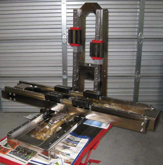
Not much to see, I'm afraid! We have been busy with some customer machines. I do have a newer photo though, I'll add that above, with a pic of the others we've been building for your interest.
Best regards,
Jason
Im looking into cnc machines at moment and not to sue if I will import 1 or build 1 or get 1 made.
After one that can to wood, plastics, alloy. up to 600mm x 600mm x 100mm cutting area.
Whats you ideas and help would be mint. :)