I started a CNC retrofit of my manual mill today. The Chevalier FM3-VK is basically a 10 x 50 Bridgeport clone, very well built and accurate, generally a very nice solid machine. It has a 3 Hp spindle motor with a variable speed drive, and takes NT30 or BT30 taper tooling (there's a handy drawbar spacer to allow use of the longer NT30 shank, hidden under the head of the drawbar).
When I purchased it, it was wired for 415 volts, 3 phase, and I only have 230 volts, single phase power available in my workshop. The spindle and coolant pump motors are dual voltage, so we swapped them to the lower voltage setting and hooked up a couple of VFD's to drive them, taking control signals from the existing switch gear - for all intents and purposes, it operates just as it would if it were connected to 3 phase power.
As I'd intended to keep this machine manual, I've fitted an Acu-Rite DRO, which will be somewhat redundant once the retrofit is complete. I'll likely leave it fitted, as it will be nice to have should I ever want to use the mill manually for the odd small job. My preference would have been for direct drive servos, however the motor sticking out the end of the table on the X axis would have come very close to the wall on that side. Accordingly, I'll be fitting the brushless servos with belt reduction to drive the screws on the X and Y axis so that I can turn the servos around, and a direct driven, fine pitch ball screw will operate the quill. The knee will remain manual for the time being. Initially, I'll be retaining the existing axis screws too, as this series of Chevalier mills has adjustable dual nuts for the X and Y, which can be tweaked to reduce the backlash to as low as .02 mm (0.0008"). A change to ball screws in the future is likely, but the timing will depend how well the existing trapezoidal screws work!
One of the goals of this conversion will be to keep the machine to it's existing footprint - no motors sticking out the front or side, as there's limited space as it is. The mll must stay operational during the upgrade, as I use it daily. I'd also like to avoid drilling or otherwise modifying the machine itself, and as I quite like the look of the machine, I'd like this upgrade to be aesthetically pleasing as much as possible too.
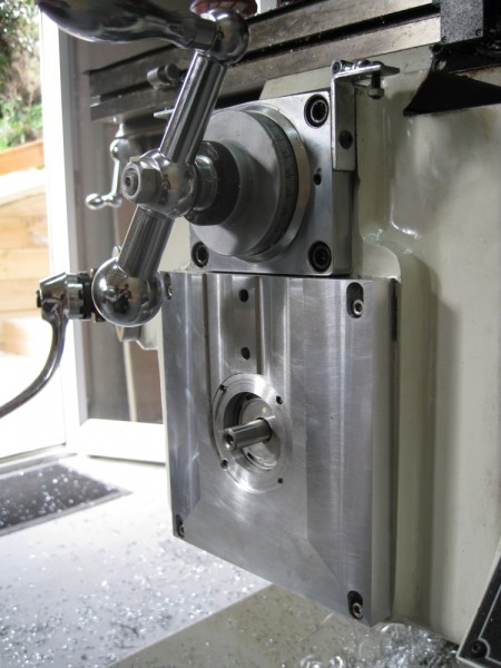
So, starting with the Y axis: I'll place the servo inside the knee, and the belt drive pulley will replace the graduated dial under the hand wheel. Conveniently, the kind people at Chevalier built it with an access hole in the front of the knee, so I'll use that, thank you!
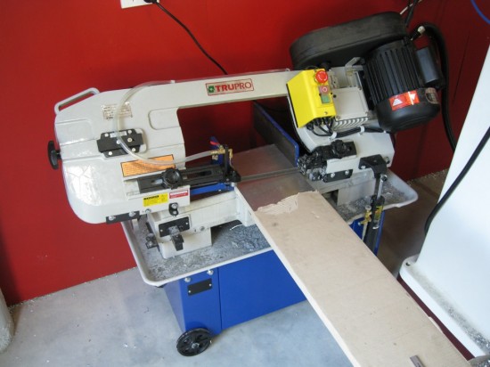
I cut a piece of 25 mm plate to form the motor mount...
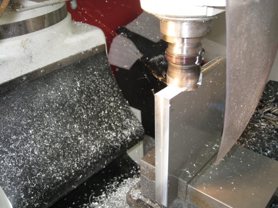
...then milled the edges square...
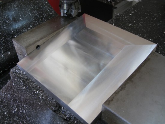
...and beveled the sides and bottom while I had the face mill fitted, for purely aesthetic reasons. I had to remove the jaws from the vise, as the plate was otherwise too big to clamp at 180 mm x 191 mm. As I wanted to be able to adjust the belt without having to access the back of the servo up inside the knee, I slotted the holes where the mounting plate attaches to the knee instead. After boring the hole for the servo mounting boss, the back of the plate is pocketed to take the square servo face plate, and 4 x M5 tappings take the stainless SHCS bolts that hold the servo in place. The face of the plate is relieved to give clearance for the pulley and belt, and a couple of threaded holes will give an attachment point for the protective belt drive cover.
My calculations suggest these servos with a belt reduction will be able to drive this mill just fine, however if I'm wrong, I've left enough clearance to switch to larger motors later.
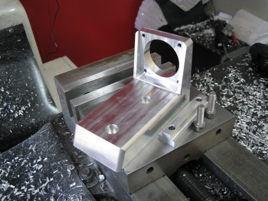
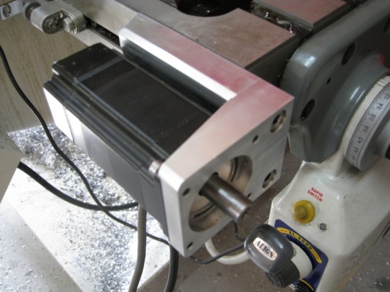
Next, the X axis. The servo will be mounted using the 'T' slot on the front of the table. I'd have preferred this motor be mounted at the back of the table, but then it could hit the column and would reduce the work envelope slightly.
The bracket attaches to the table using the long 'T' nut. The bore is a snug fit on the motor mounting boss, and another 4 x M5 SHCS fix it in place.
The top of the bracket is flush with the top of the mill table so it won't impede larger work.
Next, the Z axis. I've been looking at making the knee the Z axis, but that would be difficult without removing the knee and I don't want the mill out of action, so for now I'll continue with the plan to use the quill.
More to come soon...

Comments
can email me at shogunb at ihug.co.nz
Cheers
Splint
Best regards,
Jason
I'll be using some used BLDC servos with similar torque to the BL70-300 to test first. I'll switch to the BL70-300's if they work ok. If I find the existing screws backlash is acceptable but they need more power, then I'll fit larger servos.
The Keling 1125 oz-in servo has quite a bit more torque than the BL70-300 and in testing has been very smooth with the Granite Devices VSD-E drive, but it's a significantly larger motor. As the VSD-E drive will soon be able to control 2 axis per drive with DC servos, it would be a very good choice for this sort of conversion, as two drives could control four axis, making a very affordable system.
At this stage, I'm intending to make the quill the Z axis, yes. I haven't drawn plans, as it seems there are many variations of these machines around, and what fits one might not fit others. You're more than welcome to use the design though, I will try to ensure I take some clear photos so you can see how I've done it.
Best regards,
Jason
Thanks for taking time to respond,
Jonathan Thacher
Fairfax, Virginia
Best regards, Jason
I'll keep ya posted. Where are you Physically, ie what state, town.
Jonathan
Yes, once the conversion is finished the power feed gear might as well go. If I get to the stage where ball screws are needed I'm likely to go with NSK - it's so easy to get custom screws exactly as we want them, and we've had some remarkable test reports on them lately with C5 grade screws almost making the grade for C1.
It would be great to hear how your conversion goes. I'd have liked a genuine Bridgeport, but nice ones are pretty rare here (Hamilton, New Zealand), and 10 x 50's are even rarer!
I use mostly 6061-T651. My local Nalco branch has very good service. If you can't find what you want near you I can supply it, though shipping will get a bit steep if you're located outside New Zealand. Let me know if you want a cost!
Kind regards,
Jason